Voltage Drop Calculator
Find the voltage drop for a wire size, the smallest wire for a target drop, or the longest run a wire can serve.
Assumes stranded copper or aluminum at the conductor temperature you enter (75 °C by default), resistance only unless you add reactance; size mode also checks NEC 310.16 ampacity at 30 °C with up to 3 conductors. Free, runs in your browser. Verify with your local code and a licensed electrician before you install.
Recent
Your last 10 settings, saved only in this browser. Nothing is uploaded.
How to use the Voltage Drop Calculator
- Pick a mode in Calculate: “Voltage drop for a wire size”, “Wire size for a target drop” or “Longest run for a wire size”.
- Choose the Supply type: Single phase AC, Three phase AC or DC.
- Enter the Voltage (V). For three phase, use the line-to-line value such as 208, 240 or 480 V.
- Set Load given as. With “Current (amps)”, type the Load current (A). With “Power (watts)”, enter the Load power in W, kW or hp; for AC also set the Power factor (1 for heaters, about 0.8 to 0.9 for motors).
- Enter the One-way length in ft or m, measured along the cable route, not the round trip.
- Select the Conductor (Copper or Aluminum) and the Size system, then pick a Wire size (AWG / kcmil) or Cable size (mm²).
- In the size and length modes, set the Allowed voltage drop (%). The size mode also asks for the Insulation temperature rating (AWG only) and whether it is a Continuous load (3 hours or more).
- Open More options to change the Conductor temperature (°C), the number of Parallel sets, an optional Reactance X or the Stranded conductor (+2 % resistance) box.
- Read the result rows and any warnings.
The example buttons above the form load ready-made inputs. Copy result, Copy link and Print / save as PDF keep a record of the run, and Reset returns to the defaults.
How do you calculate voltage drop?
For single phase AC and DC, voltage drop is VD = 2 × L × I × R, where L is the one-way length, I is the load current and R is the conductor resistance per unit length. The 2 counts the outgoing and return conductors. Three phase circuits use √3 in place of 2 with the line-to-line voltage.
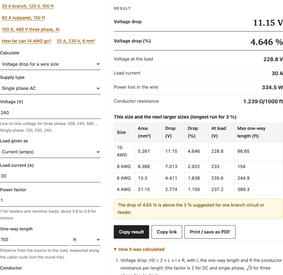
The default inputs show each step the tool prints:
- Resistance of 10 AWG stranded copper at 75 °C: 1.239 Ω per 1000 ft, worked out from the resistivity and temperature coefficient (NBS Handbook 100) plus 2 % for stranding.
- Drop: 2 × 0.15 kft × 30 A × 1.239 Ω per 1000 ft = 11.15 V.
- Percent: 11.15 V ÷ 240 V = 4.65 %, leaving 228.8 V at the load.
- Heat in the two conductors: 2 × L × I² × R = 334.5 W.
The resistance is calculated, not copied from NEC Chapter 9 Table 8, so it follows the conductor temperature you enter. Reactance is added only when you type a value.
How much voltage drop is acceptable?
The informational notes to NEC 210.19(A) and 215.2(A) suggest no more than 3 % on one branch circuit or feeder and 5 % in total from the service to the farthest outlet. They are recommendations, not enforceable limits, though designers commonly use them as targets. On 240 V, 3 % is 7.2 V; on 120 V it is 3.6 V.
The tool warns when a result passes either figure. The default 4.65 % run gets the 3 % warning; the next table row shows 8 AWG at 2.92 %, which meets it.
What is the voltage drop on 12 AWG?
A 16 A load on 100 ft of 12 AWG copper at 120 V single phase drops 6.304 V, or 5.25 %, leaving about 113.7 V at the load. That is above both suggested limits, and the tool flags the 5 % one. Switching to “Wire size for a target drop” at 3 % returns 8 AWG.
| Mode | Size | Drop | Note |
|---|---|---|---|
| Voltage drop for a wire size | 12 AWG | 6.304 V (5.25 %) | over 5 % |
| Wire size for a target drop, 3 % | 8 AWG | 2.494 V (2.08 %) | drop decides; ampacity alone needs 12 AWG |
How do I calculate voltage drop for a single-phase or 3-phase circuit?
Choose the Supply type and the tool applies the right factor: 2 for single phase AC and DC, √3 for three phase with line-to-line voltage. With the same 30 A, 240 V, 150 ft and 10 AWG copper, single phase drops 4.65 % and three phase drops 4.02 %, because √3 is smaller than 2.
| Example | Result |
|---|---|
| 40 A continuous, 240 V single phase, 200 ft, copper, 3 % | 4 AWG (2.05 %); drop decides |
| 100 A, 480 V three phase, 300 ft, aluminum, 3 % | 1/0 AWG (2.17 %); drop alone allows 1 AWG, ampacity decides |
For motors, enter the power and power factor so the tool derives the current. For battery and solar runs, the DC Voltage Drop Calculator is set up for low-voltage systems.
Worked examples
| Input | Result |
|---|---|
| 30 A, 240 V Single phase AC, 150 ft, copper, 10 AWG | 11.15 V (4.65 %) |
| 16 A, 120 V Single phase AC, 100 ft, copper, 12 AWG | 6.304 V (5.25 %) |
| 40 A, 240 V Single phase AC, 200 ft, copper, 3 % | 4 AWG (2.05 %) |
| 100 A, 480 V Three phase AC, 300 ft, aluminum, 3 % | 1/0 AWG (2.17 %) |
| 15 A, 120 V Single phase AC, 14 AWG, 3 % | 38.31 ft |
Calculated by the tool above; open it with the same values to see each step.
Questions, briefly answered
What causes voltage drop?
Current flowing through the resistance of the conductor. The drop grows with current, length and resistance, and resistance rises as the wire warms, which is why the default conductor temperature is 75 °C rather than 20 °C.
What is the voltage drop per 100 ft?
It depends on the wire, current and supply. With 30 A on 10 AWG stranded copper at 240 V single phase, 100 ft one way drops 7.434 V (3.10 %). Enter 100 ft as the One-way length to get the figure for your own circuit.
Does a longer wire cause more voltage drop?
Yes, the drop is proportional to length. The default 30 A, 10 AWG circuit drops 11.15 V at 150 ft and 22.30 V at 300 ft.
What size wire do I need to avoid voltage drop?
Some drop is unavoidable, so the goal is to stay under a target. The “Wire size for a target drop” mode returns the smallest size that meets your percentage and, for AWG sizes, also has enough ampacity under NEC 310.16, with 125 % for continuous loads.
Can I calculate voltage drop in mm2 instead of AWG?
Yes. Set Size system to “mm² (IEC 60228)” and choose a Cable size from 0.5 to 630 mm². The “32 A, 230 V, 6 mm²” example gives 9.125 V (3.97 %) over 40 m. Metric sizes are checked for drop only, not current rating.
Is copper or aluminum better for reducing voltage drop?
Copper drops less at the same size. The default circuit drops 4.65 % in copper and 7.65 % in aluminum, so aluminum usually needs a size or two larger.
How far can 14 AWG go?
At 15 A and 120 V single phase, 14 AWG copper stays within 3 % for 38.31 ft one way. The “How far can 14 AWG go?” example loads this case in the longest-run mode.
Does stranded wire change the result?
Slightly. With Stranded conductor (+2 % resistance) ticked, the default circuit drops 11.15 V; unticked, it drops 10.93 V.
Related tools
- DC Voltage Drop Calculator: for 12 V, 24 V and 48 V battery and solar runs.
- Wire Size Calculator: pick a size from the load, run length and insulation.
- Wire Ampacity Calculator: check how many amps a size can carry after derating.
- Wire Gauge Chart: compare AWG diameters, areas and resistance.
- AWG to mm2 Converter: convert a size between AWG and mm².
- Cable Size Calculator: size a cable when you work in mm².
- Wire Size for 50 Amp Circuit: ranges, welders and subpanels on 50 A.
- Battery Cable Size Calculator: inverter and battery bank cables.
- Wire and Cable Calculators: every wire tool on the site.