
Ambient Temperature Correction Calculator
Calculate conductor ampacity derating factors for high ambient temperatures and rooftop raceways per NEC Table 310.15(B)(1).
Pro calculator. The examples run free for everyone, with full results and steps; 3 results a month with your own numbers are free, then Pro. Always free: 9 calculators + 5 charts.
Calculates wire and electrical parameters per NEC 2023. Runs in your browser. Verify with your local code and a licensed electrician before you install.
Recent
Your last 10 settings, saved only in this browser. Nothing is uploaded.
How to use the Ambient Temperature Correction Calculator
- Select the conductor size (14 AWG to 500 kcmil) and the material, copper or aluminum (aluminum starts at 12 AWG).
- Select the insulation temperature rating (60 °C, 75 °C or 90 °C) - the derating starts from this column of Table 310.16.
- Select the temperature rating of the equipment terminals (75 °C or 60 °C); the final ampacity may not exceed the table value in that column (110.14(C)).
- Enter the highest expected ambient temperature and choose °C or °F.
- Choose the rooftop option only for a raceway or cable in direct sunlight less than 3/4 in (19 mm) above the roof (NEC 2023 310.15(B)(2) adds 33 °C; XHHW-2 is exempt).
- Select how many current-carrying conductors share the raceway or cable (310.15(C)(1)); see 310.15(E) for when a neutral counts.
- Read the allowable ampacity, both factors, the effective ambient and the largest standard breaker at or below the ampacity, with the 240.4(D) small-conductor limits applied. Make sure the load and the breaker you plan fit under it, then compare the answer with your local code and confirm it with a licensed electrician before you buy wire or pull anything.
Example: 10 AWG THHN copper (40 A in the 90 °C column) in a 46 °C attic with six current-carrying conductors gives 40 × 0.82 × 0.80 = 26.24 A.
Temperature Correction and Conductor Ampacity Derating Rules
The ampacity of an insulated electrical conductor represents the maximum current in amperes it can carry continuously without exceeding its thermal insulation temperature rating.
Why Baseline Temperature Matters (NEC Table 310.16)
NEC Table 310.16 ampacities assume an ambient temperature of 30 °C (86 °F). If ambient air temperature rises above 30 °C, the temperature gradient between the copper conductor and ambient air narrows. Heat dissipation slows, meaning less current can flow before insulation reaches its maximum thermal threshold (e.g., 90 °C for THHN/THWN-2).
Under NEC 310.15(B)(1), the temperature correction factor ($K_t$) is mathematically calculated using the formula: $$K_t = \sqrt{\frac{T_c - T_a}{T_c - T_0} }$$ Where $T_c$ is conductor rated insulation temperature (60 °C, 75 °C, or 90 °C), $T_a$ is actual operating ambient temperature, and $T_0$ is the base table reference temperature of 30 °C.
Compound Derating: Temperature Plus Bundling (NEC 310.15(C)(1))
When more than three current-carrying conductors are routed in a single conduit, mutual heating occurs. NEC Table 310.15(C)(1) specifies bundle adjustment factors ($K_b$):
- 4 to 6 Conductors: 80% (0.80)
- 7 to 9 Conductors: 70% (0.70)
- 10 to 20 Conductors: 50% (0.50)
The total corrected allowable ampacity ($I_{\text{allow} }$) must be calculated using both factors simultaneously: $$I_{\text{allow} } = I_{\text{table} } \times K_t \times K_b$$
Example:
Consider 6 current-carrying 10 AWG THHN copper conductors in EMT conduit installed in an attic where ambient temperatures reach 115 °F (46 °C):
- Base 90 °C Table 310.16 ampacity: 40 Amperes.
- Table 310.15(B)(1) temperature correction for 90 °C at 46 °C: 0.82.
- Table 310.15(C)(1) bundle adjustment for 6 conductors: 0.80.
- Corrected Ampacity: $40\text{A} \times 0.82 \times 0.80 = 26.24\text{A}$. The 75 °C terminal value of 10 AWG copper (35 A) does not limit it here, so 26.24 A is the allowable ampacity: the load must stay at or below 26.24 A, 25 A is the largest standard breaker below it, and 240.4(B) may allow the next size up (30 A) for such a load - but a 30 A load is too much.
Worked examples
| Input | Result |
|---|---|
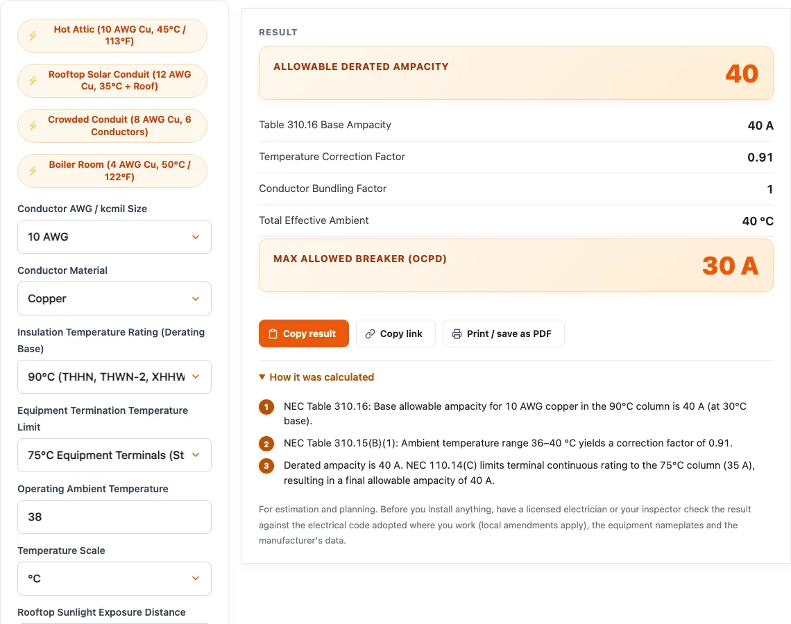
| 10 Cu (90 °C) at 38 °C | Table 40 A, allowable 35 A (factor 0.91, max 30 A OCPD) |
| 12 Cu (90 °C) at 42 °C, on a sunny rooftop under 3/4 in (+33 °C) | Table 30 A, allowable 15 A (factor 0.50, max 15 A OCPD) |
| 8 Al (90 °C) at 35 °C, 4-6 current-carrying conductors | Table 45 A, allowable 34.56 A (factor 0.96, max 30 A OCPD) |
| 4 Cu (75 °C) at 45 °C | Table 85 A, allowable 69.7 A (factor 0.82, max 60 A OCPD) |
Calculated by the tool above; open it with the same values to see each step.
Questions, briefly answered
Common questions regarding temperature correction factors and ampacity derating per NEC 310.15:
When do I need to derate wire for ambient temperature?
You must apply temperature derating whenever the ambient temperature surrounding a raceway or cable exceeds 86 °F (30 °C). High-temperature environments requiring derating include building attics, rooftop conduit runs exposed to sunlight, boiler rooms, industrial process facilities, and outdoor electrical installations in hot climates.
Can I use the 90 °C column for derating even if my breaker is rated for 75 °C?
Yes! Under NEC 110.14(C) and the introductory notes to Table 310.16, you are permitted to start your temperature and conductor bundling derating calculations from the 90 °C ampacity column of THHN wire, provided that the final calculated ampacity does not exceed the 75 °C terminal rating of the circuit breaker. This is one of the primary advantages of installing 90 °C rated wire.
How does rooftop solar heat affect conduit wire size?
Raceways and cables lying in direct sunlight just above a roof run much hotter than the air. In the 2023 NEC, 310.15(B)(2) adds 33 °C (60 °F) to the ambient only where the raceway or cable is less than 3/4 in (19 mm) above the roof; at 3/4 in or more no adder applies, and Type XHHW-2 is exempt. (The older 22 °C / 17 °C / 14 °C adders for greater heights were in the 2017 NEC and were removed in 2020.) Mounting the conduit on supports 3/4 in or taller therefore avoids the adder.
Do neutral conductors count as current-carrying conductors for bundling?
Under NEC 310.15(E)(1), a neutral conductor that carries only the unbalanced current from other conductors of the same circuit is not counted as a current-carrying conductor for bundling derating. However, in 3-wire circuits consisting of 2 phase conductors and the neutral of a 4-wire, 3-phase wye system, the neutral carries current comparable to the phase conductors and must be counted.