
Equipment Grounding Conductor Calculator
Size circuit equipment grounding conductors per NEC Table 250.122 with automatic proportional upsizing per NEC 250.122(B).
Pro calculator. The examples run free for everyone, with full results and steps; 3 results a month with your own numbers are free, then Pro. Always free: 9 calculators + 5 charts.
Calculates wire and electrical parameters per NEC 2023. Runs in your browser. Verify with your local code and a licensed electrician before you install.
Recent
Your last 10 settings, saved only in this browser. Nothing is uploaded.
How to use the Equipment Grounding Conductor Calculator
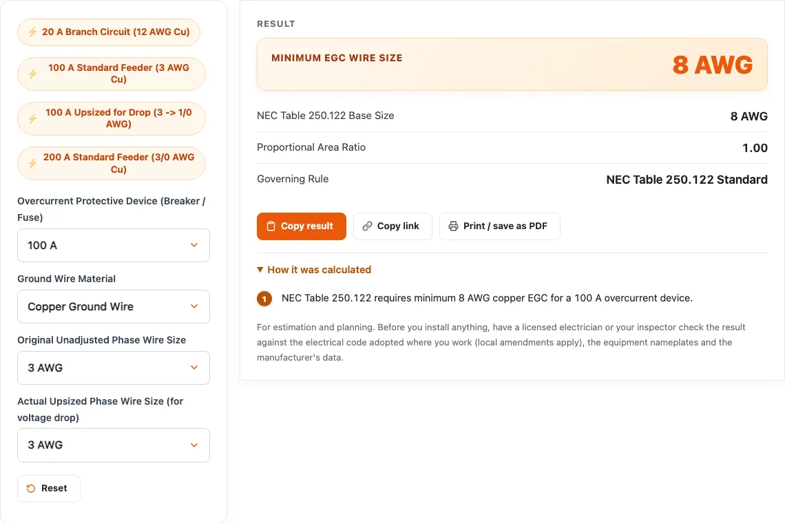
- Select the rating of the breaker or fuse ahead of the circuit (15 A to 1200 A).
- Select the material of the equipment grounding wire: copper, or aluminum / copper-clad aluminum.
- Select the minimum phase conductor size the circuit would need for its ampacity.
- Select the phase size you are actually installing. If it is larger (for example for voltage drop), 250.122(B) increases the EGC in the same circular-mil proportion; if it is the same, the Table 250.122 size applies.
- Read the result: the Table 250.122 size, the area ratio and the required EGC, never larger than the circuit conductors (250.122(A)).
- Where several circuits share a raceway, size one EGC for the largest breaker (250.122(C)); for parallel runs see 250.122(F). Confirm with your local code and a licensed electrician.
Example: a 100 A feeder needs 3 AWG copper for its ampacity, and Table 250.122 gives an 8 AWG copper EGC. If the run is long and you install 1/0 AWG copper to keep voltage drop down, the ratio of the areas is 105,600 ÷ 52,620 = 2.007. The EGC must grow by the same ratio: 16,510 × 2.007 = 33,133 circular mils, which is more than 6 AWG (26,240) and less than 4 AWG (41,740), so the EGC becomes 4 AWG copper. The result never exceeds the size of the circuit conductors themselves.
Sizing Equipment Grounding Conductors per NEC 250.122
The Equipment Grounding Conductor (EGC) provides the low-impedance fault return path required to safely trip circuit breakers during an insulation breakdown or line-to-chassis fault.
Base Sizing from NEC Table 250.122
Under standard conditions, the EGC is sized solely from the rating of the overcurrent protective device (OCPD) ahead of the circuit:
- 15A Breaker: 14 AWG copper (12 AWG aluminum).
- 20A Breaker: 12 AWG copper (10 AWG aluminum).
- 30A Breaker: 10 AWG copper (8 AWG aluminum).
- 40A / 50A Breaker: 10 AWG copper (8 AWG aluminum).
- 60A Breaker: 10 AWG copper (8 AWG aluminum).
- 100A Breaker: 8 AWG copper (6 AWG aluminum).
- 200A Breaker: 6 AWG copper (4 AWG aluminum).
- 400A Breaker: 3 AWG copper (1 AWG aluminum).
- 600A Breaker: 1 AWG copper (2/0 aluminum).
Where multiple circuits are installed in a single raceway, cable, or cable tray, NEC 250.122(C) permits a single common EGC sized according to the largest overcurrent device protecting conductors in that raceway.
Proportional Upsizing for Voltage Drop (NEC 250.122(B))
When branch circuit or feeder conductors are upsized to compensate for voltage drop on long runs, NEC 250.122(B) mandates that the equipment grounding conductor must be increased in size proportionately according to the circular mil area of the ungrounded conductors: $$\text{Required cmil}{\text{EGC} } = \text{Base cmil}{\text{EGC} } \times \left( \frac{\text{Upsized Phase cmil} }{\text{Standard Minimum Phase cmil} } \right)$$
Real-World Example:
Consider a 100-amp feeder circuit. Table 250.122 requires an 8 AWG copper EGC (16,510 circular mils), while standard phase conductors are 3 AWG copper (52,620 circular mils). If a 300-foot run forces the electrician to upsize the phase conductors to 1/0 AWG copper (105,600 circular mils) to control voltage drop:
- Circular mil ratio: $105{,}600 / 52{,}620 = 2.007$
- Adjusted EGC area: $16{,}510 \times 2.007 = 33{,}135$ circular mils.
- Checking NEC Chapter 9 Table 8, a 6 AWG conductor (26,240 cmils) is too small. The EGC must be upsized to 4 AWG copper (41,740 cmils).
Failing to enlarge the ground conductor increases fault loop impedance, potentially delaying breaker trip times during line-to-ground faults.
Worked examples
| Input | Result |
|---|---|
| 100 A OCPD (Cu EGC, phase 3 -> 3) | 8 AWG Cu EGC (NEC Table 250.122 Standard) |
| 100 A OCPD (Cu EGC, phase 3 -> 1/0) | 4 AWG Cu EGC (NEC 250.122(B) Proportional) |
| 200 A OCPD (Cu EGC, phase 3/0 -> 250) | 4 AWG Cu EGC (NEC 250.122(B) Proportional) |
| 60 A OCPD (Al EGC, phase 6 -> 4) | 4 AWG Al EGC (NEC 250.122(B) Proportional) |
Calculated by the tool above; open it with the same values to see each step.
Questions, briefly answered
Common questions regarding equipment grounding conductor sizing and proportional expansion rules:
Why must the ground wire be upsized when hot wires are upsized for voltage drop?
Under NEC 250.122(B), when phase conductors are enlarged to overcome resistance on long runs, the ground wire must be enlarged by the same circular mil proportion. If the hot wires are upsized but the ground wire remains small, the impedance of the ground return path becomes too high during a short circuit, preventing the circuit breaker from tripping fast enough to clear the fault safely.
Can a single ground wire serve multiple branch circuits in one conduit?
Yes. Under NEC 250.122(C), a single common equipment grounding conductor can serve multiple circuits in the same conduit or cable tray. The common EGC only needs to be sized for the single largest overcurrent protective device protecting conductors in that conduit run.
What size ground wire do I need for a 50-amp circuit?
According to NEC Table 250.122, a 50-amp circuit breaker requires a minimum 10 AWG copper equipment grounding conductor (or 8 AWG aluminum). If the phase conductors are made larger than the size the circuit needs for ampacity (for example for voltage drop on a long run), the ground wire must be enlarged in the same proportion per NEC 250.122(B).
Can metal conduit serve as the equipment grounding conductor?
Yes, certain metallic raceways including EMT (Electrical Metallic Tubing), RMC (Rigid Metal Conduit), and IMC (Intermediate Metal Conduit) are recognized as equipment grounding conductors under NEC 250.118, provided all fittings and couplings are listed, made up wrench-tight, and maintain metallic continuity.