
Generator Interlock Cable Calculator
Calculate conductor gauge, generator power inlet box ratings, and mechanical breaker interlocks per NEC Article 702.
Pro calculator. The examples run free for everyone, with full results and steps; 3 results a month with your own numbers are free, then Pro. Always free: 9 calculators + 5 charts.
Calculates wire and electrical parameters per NEC 2023. Runs in your browser. Verify with your local code and a licensed electrician before you install.
Recent
Your last 10 settings, saved only in this browser. Nothing is uploaded.
How to use the Generator Interlock Cable Calculator
- Select the inlet rating that matches your generator’s largest receptacle (20A, 30A or 50A) and the voltage (120/240V or 120V only).
- Enter the total one-way length: the generator cord plus the hardwired run from the inlet box to the panel. The voltage drop is checked over the whole length.
- Under More options, set the voltage drop target, ambient temperature and number of conductors in the raceway if they differ from the defaults.
- For a 50A inlet, select the hardwired run’s conductor material (copper or aluminum); the cord is always copper.
- The hardwired run is sized from the 60 °C column (NEC 110.14(C)(1)(a), circuits of 100A or less), which also covers NM-B.
- Review the calculated results panel: the calculator determines the required circuit breaker backfeed rating, selects minimum conductor gauge for both cord and interior wiring, sizes the copper cord from NEC Table 400.5(A)(1) and computes the voltage drop over the total length. Conduit size is not calculated.
- Check your generator neutral bonding configuration to confirm whether floating neutral operation is needed for your mechanical interlock setup to avoid parallel return paths.
- Print the installation checklist and voltage drop calculations to ensure your home standby setup complies fully with NEC Article 702 and local utility interconnection guidelines.
- Inspect panel mechanical interlock bracket compatibility with your specific load center brand and catalogue model before beginning physical installation.
Generator Interlock and Inlet Wiring Rules per NEC 702
Optional standby generator systems installed in residential homes allow homeowners to maintain essential refrigeration, heating, lighting, and well pump circuits during utility grid power outages.
Mechanical Interlocks vs. Automatic Transfer Switches
NEC 702.5 requires transfer equipment that keeps the generator and the utility from being connected together:
- Mechanical Interlock Plate: A metal sliding bracket attached to the front of the electrical panel deadfront cover. It physically blocks the generator backfeed breaker from switching ON unless the main 200A or 100A utility breaker is switched completely OFF. This low-cost, code-compliant solution permits backfeeding any branch circuit in the main panel up to generator capacity.
- Backfeed Breaker Retaining Strap (NEC 408.36(D)): Because the generator backfeeds power into a branch breaker, that breaker must be secured in place by an additional mechanical retaining screw or strap to prevent accidental dislodgement under load.
Sizing Conductor Gauges for 30A and 50A Inlets
Residential generator hookups standardly use one of two NEMA configurations:
- 30-Amp 120/240V System (NEMA L14-30): Suitable for generators up to about 7,200 running watts ($30\text{A} \times 240\text{V} = 7{,}200\text{W}$). Requires 10 AWG copper for the outdoor cord (30A in NEC Table 400.5(A)(1)) and for the building wiring (10/3 NM-B or 10 AWG THHN).
- 50-Amp 120/240V System (CS6365 / NEMA 14-50 inlet): Suitable for generators up to 12,000 running watts ($50\text{A} \times 240\text{V} = 12{,}000\text{W}$). Requires 6 AWG copper for the building wiring (6 AWG THHN or 6/3 NM-B, 55A at 60 °C) and a 6 AWG 4-conductor flexible cord (8 AWG cord is only 40A in NEC Table 400.5(A)(1)).
Compound Voltage Drop Across Cord and Building Wiring
A critical engineering detail often overlooked is that voltage drop occurs across two distinct wiring segments:
- The portable rubber cord between the generator and the inlet box (typically 15 to 50 feet).
- The permanent building raceway from the inlet box to the electrical panel (often 20 to 100 feet).
Because portable generators operate near full rated current during emergency outages, total accumulated voltage drop across both segments must be controlled to within 3% to 4% at 240V. Excessive voltage drop can cause sensitive electronics, refrigerator compressors, and well pumps to stall or overheat during backup operation.
Worked examples
| Input | Result |
|---|---|
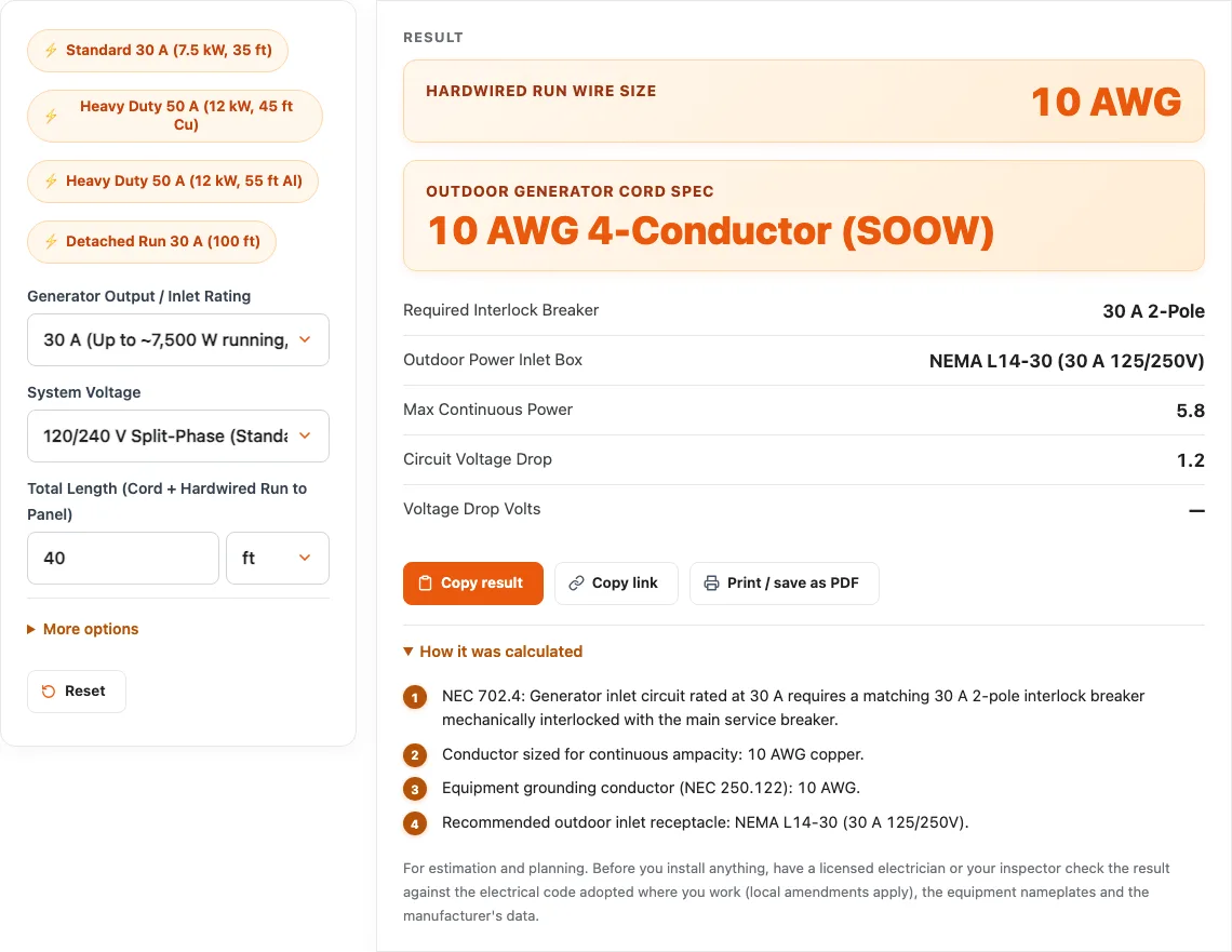
| 30 A generator inlet at 240 V (40 ft) | 10 AWG wire with 30 A 2-Pole breaker (NEMA L14-30 (30 A 125/250 V), 1.2 % drop) |
| 50 A generator inlet at 240 V (50 ft) | 6 AWG wire with 50 A 2-Pole breaker (NEMA 14-50 / CS6365 (50 A 125/250 V), 1 % drop) |
| 50 A generator inlet at 240 V (60 ft) | 4 AWG wire with 50 A 2-Pole breaker (NEMA 14-50 / CS6365 (50 A 125/250 V), 1.3 % drop) |
| 30 A generator inlet at 240 V (120 ft) | 8 AWG wire with 30 A 2-Pole breaker (NEMA L14-30 (30 A 125/250 V), 2.3 % drop) |
Calculated by the tool above; open it with the same values to see each step.
Questions, briefly answered
Common questions regarding portable generator inlet boxes and interlock wiring rules:
What size wire do I need for a 50-amp generator inlet box?
A 50-amp 120/240V generator inlet box requires 6 AWG copper THHN conductors in conduit or 6/3 NM-B Romex cable inside building walls. The outdoor portable generator cord must be a listed 6 AWG 4-conductor flexible cable (such as SOOW or STW) terminated with approved NEMA 14-50 or CS6364 50A connectors.
Why is a 4-wire cord required for a portable generator?
Under NEC 250.30 and 702.11, modern generator hookups require four wires: two ungrounded hots (carrying 240V across phases and 120V to neutral), one grounded neutral conductor (carrying unbalanced 120V return loads), and one equipment grounding conductor. This keeps neutral return current separated from the metal chassis, preventing dangerous shock hazards.
Do I need to remove the neutral-ground bonding jumper on my portable generator?
If your generator feeds the home panel through a standard mechanical interlock where the main neutral is not switched, the panel already has a neutral-ground bond. Operating a generator with its internal neutral bonded creates a parallel return path across the ground wire. Generator makers and inspectors generally require the generator’s neutral bonding jumper to be disconnected (making it a floating neutral) when connected to a home with an unswitched neutral interlock.
Can I backfeed a generator through an ordinary dryer receptacle?
No. Backfeeding a generator through an existing dryer outlet using a homemade male-to-male cord (suicide cord) is illegal, extremely dangerous, and a direct NEC violation. Exposed prongs carry live 240V electricity, and failing to mechanically isolate the main utility breaker can electrocute utility line workers restoring power down the street.