
Motor Circuit Breaker Calculator
Determine motor full-load amperes, branch conductor gauge, inverse time circuit breaker, and overload protection per NEC Article 430.
Pro calculator. The examples run free for everyone, with full results and steps; 3 results a month with your own numbers are free, then Pro. Always free: 9 calculators + 5 charts.
Calculates wire and electrical parameters per NEC 2023. Runs in your browser. Verify with your local code and a licensed electrician before you install.
Recent
Your last 10 settings, saved only in this browser. Nothing is uploaded.
How to use the Motor Circuit Breaker Calculator
- Select the motor horsepower (1/6 hp to 200 hp), the phase and the rated motor voltage (single-phase 115-230 V up to 10 hp; three-phase 200-575 V from 1/2 hp).
- Select the service factor / temperature-rise group: SF 1.15 or more or a marked rise of 40 °C or less (overloads at 125 %), or all other motors (115 %).
- Optionally enter the nameplate full-load current under More options: overloads are set from it (430.32), not from the table.
- Read the table full-load current (430.248 / 430.250), the minimum conductor ampacity at 125 % (430.22) and the smallest copper size at 75 °C terminals.
- Read the maximum inverse-time breaker (250 %) and dual-element fuse (175 %) ratings, each rounded up to the next standard size as Table 430.52(C)(1) Exception 1 allows.
- Check the disconnect, controller and conduit fill separately, because this calculator sizes only the conductors, breaker, fuse and overload. Confirm the result with your local code and a licensed electrician.
Example: a 10 hp, 230 V three-phase motor has a table full-load current of 28 A. The branch conductors need at least 28 × 1.25 = 35 A, which is 10 AWG copper at 75 °C terminals. The inverse-time breaker may be up to 28 × 2.5 = 70 A, and a dual-element fuse up to 28 × 1.75 = 49 A, rounded up to 50 A. If the nameplate says 26 A and the service factor is 1.15, the overload relay may be set at up to 26 × 1.25 = 32.5 A.
NEC Article 430 Rules for Sizing Motor Branch Circuits
Wiring an electric motor differs fundamentally from wiring resistive lighting or electric heating loads. A motor branch circuit separates overload protection from short-circuit and ground-fault protection.
Why NEC Table FLC Governs Conductor and Breaker Sizing
Under NEC 430.6(A)(1), engineers and electricians are strictly prohibited from using the motor nameplate current rating when sizing branch conductors, disconnect switches, and short-circuit protective devices. Instead, conductors and breakers must be sized using the standard full-load currents (FLC) published in:
- NEC Table 430.248: Full-Load Currents in Amperes for Single-Phase AC Motors.
- NEC Table 430.250: Full-Load Currents in Amperes for Three-Phase AC Motors.
The actual motor nameplate current is used exclusively for sizing running thermal overload protection (heaters and electronic overload relays) per NEC 430.32. This standard ensures that if a motor burns out and is replaced with a motor of identical horsepower from a different manufacturer with a lower power factor or efficiency, the installed wiring and breakers remain fully code-compliant.
Conductor Ampacity Sizing (NEC 430.22)
Conductors supplying a single motor must have an ampacity not less than 125 percent of the motor table full-load current rating per NEC 430.22: $$\text{Conductor Ampacity} \ge \text{Table FLC} \times 1.25$$
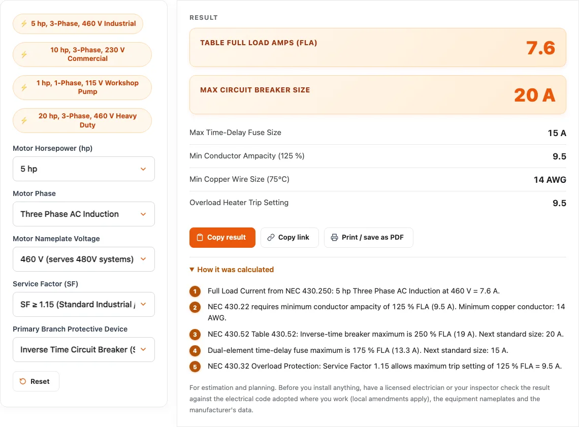
For example, a 5 HP three-phase 460V motor has a Table 430.250 FLC of 7.6 amperes. The minimum branch conductor ampacity is $7.6 \times 1.25 = 9.5$ amperes. Under standard terminal rules, 14 AWG copper wire (rated 20A at 75 °C) provides compliant ampacity.
Motor Short-Circuit and Ground-Fault Protection (NEC 430.52)
Because electric motors draw high inrush currents upon starting, standard circuit breakers would trip instantly if sized to match conductor ampacity. NEC Table 430.52 permits sizing short-circuit and ground-fault protective devices up to specific percentage limits of table FLC:
- Inverse Time Breakers: Maximum 250% of Table FLC. If 250% does not correspond to a standard breaker size (NEC 240.6), the next higher standard rating is permitted (or up to 400% under exception rules if the motor still fails to start).
- Dual-Element Time-Delay Fuses: Maximum 175% of Table FLC (up to 225% if needed to start).
- Non-Time-Delay Fuses: Maximum 300% of Table FLC.
For our 7.6A motor example, multiplying by 250% yields $7.6 \times 2.50 = 19.0$ amperes. Sizing up to the next standard rating allows a 20A circuit breaker protecting a circuit wired with 14 AWG conductor. Overload relays in the motor starter protect the wire from long-term low-grade overheating.
Worked examples
| Input | Result |
|---|---|
| 5 hp, three-phase, 460 V motor (table FLC 7.6 A) | Max 20 A breaker, 15 A fuse; wire 14 AWG Cu; overload about 9.5 A (set from the nameplate current) |
| 10 hp, three-phase, 230 V motor (table FLC 28 A) | Max 70 A breaker, 50 A fuse; wire 10 AWG Cu; overload about 35 A (set from the nameplate current) |
| 1 hp, single-phase, 115 V motor (table FLC 16 A) | Max 40 A breaker, 30 A fuse; wire 14 AWG Cu; overload about 20 A (set from the nameplate current) |
| 20 hp, three-phase, 460 V motor (table FLC 27 A) | Max 70 A breaker, 50 A fuse; wire 10 AWG Cu; overload about 31.05 A (set from the nameplate current) |
Calculated by the tool above; open it with the same values to see each step.
Questions, briefly answered
Common questions regarding electric motor branch circuit calculations and NEC Article 430 requirements:
Why is the circuit breaker size much larger than the wire ampacity for a motor?
Under NEC Article 430, the branch circuit breaker provides short-circuit and ground-fault protection only. High starting inrush currents require sizing the breaker up to 250% of motor full-load amperes to allow the motor to accelerate without tripping. Conductor thermal overload protection is handled downstream by thermal or electronic overload relays in the motor starter, which trip if continuous operating current exceeds 115% to 125% of nameplate rating.
Should I size motor wire using the motor nameplate or NEC tables?
Per NEC 430.6(A)(1), you must use the standard tables (Table 430.248 for single-phase and Table 430.250 for three-phase) to determine full-load current for sizing branch conductors, switches, and circuit breakers. Motor nameplate current is used only to select the thermal overload protection setting on the starter.
What is the maximum breaker size for a 10 HP 230V 3-phase motor?
From NEC Table 430.250, a 10 HP 230V 3-phase motor has a full-load current of 28 amperes. Sizing branch conductors at 125% requires an ampacity of $28 \times 1.25 = 35$ amperes: 10 AWG copper (35 A) where the terminals are rated 75 °C, 8 AWG copper where they are rated 60 °C. For inverse-time circuit breakers, Table 430.52(C)(1) permits 250%, which equals $28 \times 2.50 = 70$ amperes, so 70 A is the maximum breaker; overload protection is then set from the nameplate current.
How are motor overload heaters sized differently from the circuit breaker?
Motor overload protection guards against prolonged operating overloads that can burn out motor windings. Under NEC 430.32, thermal overloads are sized based on actual motor nameplate current (not table FLC): typically 125% of nameplate rating for motors with a service factor (SF) of 1.15 or greater, and 115% for motors with a 1.0 service factor.