
Electric Welder Wire Size & Breaker Calculator
Determine minimum conductor gauge, effective continuous current, and maximum allowed breaker rating for MIG, TIG, and Stick welders.
Pro calculator. The examples run free for everyone, with full results and steps; 3 results a month with your own numbers are free, then Pro. Always free: 9 calculators + 5 charts.
Calculates wire and electrical parameters per NEC 2023. Runs in your browser. Verify with your local code and a licensed electrician before you install.
Recent
Your last 10 settings, saved only in this browser. Nothing is uploaded.
How to use the Welder Wire Size Calculator
- Enter the welder rated primary input current (I1) in amperes found on the welder technical nameplate at maximum rated output.
- Enter the machine rated duty cycle percentage (standard workshop welders operate at 20%, 30%, 40%, 60%, or 100% duty cycle).
- Select the supply voltage (the multipliers used are those of NEC Table 630.11(A) for non-motor-generator arc welders: transformer and inverter MIG, TIG and stick machines).
- Specify one-way circuit distance in feet from the main breaker panel to the welder NEMA 6-50 receptacle.
- Select conductor material (copper or aluminum); the conductor is sized from the 75 °C column.
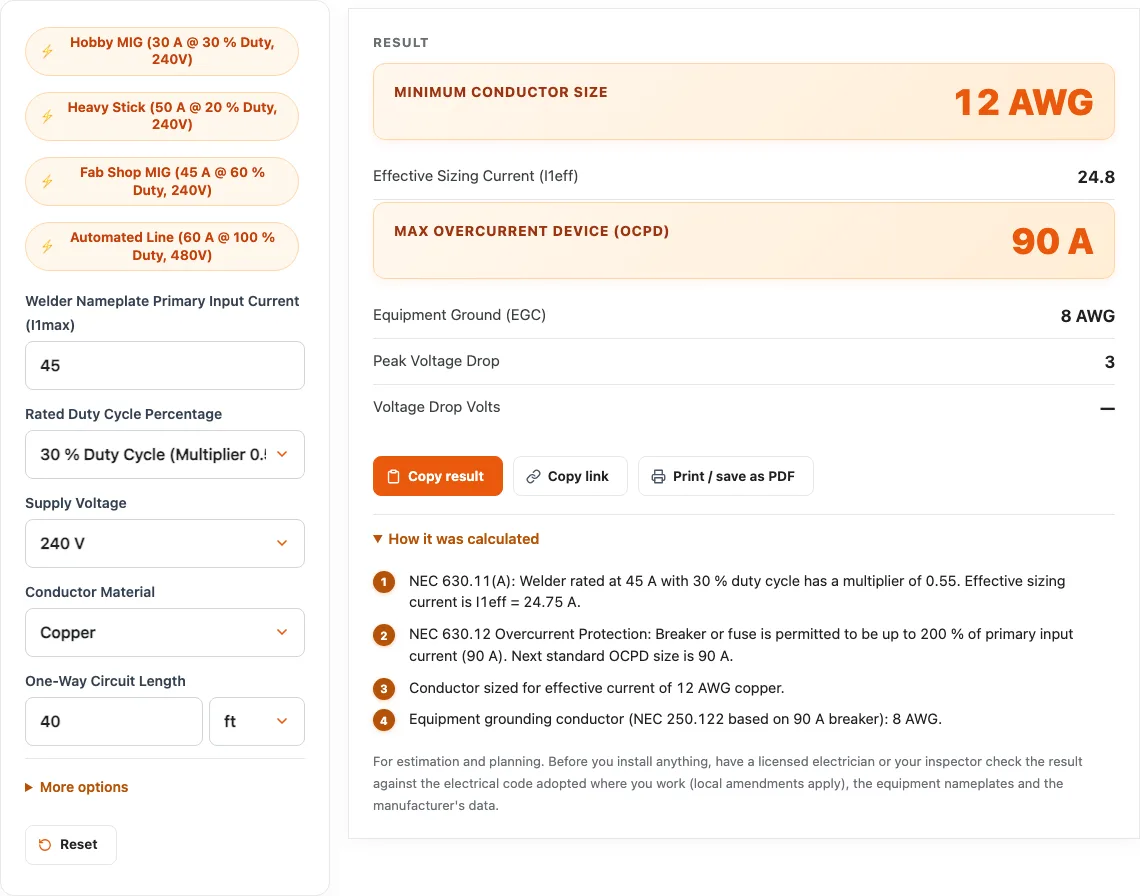
- Review the calculated results panel: the calculator applies the official duty-cycle multiplication factor from NEC Table 630.11(A), determines the required effective current rating (I1eff), calculates conductor gauge from NEC Table 310.16, computes voltage drop, and gives the largest breaker allowed by both parts of NEC 630.12 (200% of I1max and 200% of the conductor ampacity); if that would be below I1max the wire is upsized.
- Confirm receptacle rating and ensure the branch circuit outlet is dedicated solely to welding equipment with proper identification labels.
- Save or copy the duty-cycle derivation report to demonstrate code compliance under NEC 630 for your workshop or commercial fabrication shop permit inspection.
- Verify that conductor termination lugs in the disconnect box or receptacle are rated for the selected copper wire gauge and torque accordingly.
- Review the printed audit calculations with your licensed electrical contractor or master electrician before purchasing electrical materials.
Understanding NEC Article 630 for Arc Welder Branch Circuits
Electric arc welding involves extreme thermal cycling: dead short-circuits during arc strike followed by high current flow while welding, interspersed with idle cooling intervals while the operator chips slag, moves clamps, and reloads wire.
Sizing Conductors for Duty Cycle (NEC 630.11(A))
Conductors do not heat up instantaneously; thermal mass in copper allows wire to absorb brief current peaks without insulation degradation. NEC Table 630.11(A) gives duty cycle multipliers for non-motor-generator arc welders (motor-generator welders have their own column; resistance welders follow 630.31):
- 100% Duty Cycle: Multiplier = 1.00
- 80% Duty Cycle: Multiplier = 0.89
- 60% Duty Cycle: Multiplier = 0.78
- 50% Duty Cycle: Multiplier = 0.71
- 40% Duty Cycle: Multiplier = 0.63
- 30% Duty Cycle: Multiplier = 0.55
- 20% Duty Cycle: Multiplier = 0.45
Example Calculation:
A popular 200A MIG welder draws 36A rated primary current at a 30% duty cycle. $$\text{Effective Current } (I_{1\text{eff} }) = 36\text{A} \times 0.55 = 19.8\text{A}$$ Per NEC 630.11, the branch circuit conductor only needs an ampacity of 19.8 amperes. Sizing from the 75 °C column of NEC Table 310.16, 14 AWG copper wire (rated 20A) already meets 630.11; the breaker then decides the wire size, see below.
Sizing Breakers Up to 200% (NEC 630.12)
While the wire is sized for only 19.8A effective current, striking an arc can momentarily draw 50A to 70A. An ordinary 20A circuit breaker would nuisance trip instantly.
To resolve this, NEC 630.12 allows the overcurrent protective device to be rated or set at not more than 200 percent of the rated primary current: $$\text{Max Breaker} = 36\text{A} \times 2.00 = 72\text{A} \rightarrow \text{Next standard size: 70A or 80A}$$
NEC 630.12(B) also limits the breaker to 200% of the conductor ampacity: 14 AWG (20 A) allows only 40 A, below the 36 A machine’s needs with margin; 12 AWG (25 A) allows 50 A and 10 AWG (35 A) allows 70 A. So this welder gets 12 AWG on a 50 A breaker, or 10 AWG on up to 70 A. The welder’s internal thermal cutout protects the machine from sustained overloads, while the breaker provides short-circuit protection.
Worked examples
| Input | Result |
|---|---|
| 45 A welder at 30 % duty cycle (240 V, 40 ft) | 12 AWG Cu conductor (effective 24.8 A) with 50 A breaker (3 % drop) |
| 50 A welder at 20 % duty cycle (240 V, 50 ft) | 10 AWG Cu conductor (effective 22.5 A) with 70 A breaker (2.6 % drop) |
| 60 A welder at 60 % duty cycle (240 V, 60 ft) | 8 AWG Cu conductor (effective 46.8 A) with 100 A breaker (2.3 % drop) |
| 30 A welder at 100 % duty cycle (240 V, 30 ft) | 10 AWG Cu conductor (effective 30 A) with 60 A breaker (0.93 % drop) |
Calculated by the tool above; open it with the same values to see each step.
Questions, briefly answered
Common questions regarding welder circuit wiring rules and duty cycle calculations:
Why can a welder use a 50-amp breaker on 10 AWG wire?
Under NEC Article 630, welders operate on a duty cycle with cooling pauses. NEC 630.11 permits conductors to be sized to effective continuous thermal current ($I_{1\text{eff} }$), while NEC 630.12 allows circuit breakers to be sized up to 200% of rated primary current to prevent nuisance tripping during arc striking. The welder internal thermal overload protector protects the circuit from sustained overloads.
What size breaker and wire do I need for a standard 240V workshop welder?
Most 240V workshop welders utilize a NEMA 6-50 receptacle. For welders with rated primary current up to 36A at 30% to 40% duty cycle, standard practice is installing 8 AWG or 6 AWG copper conductors paired with a 50-amp circuit breaker. This satisfies NEC 630 while accommodating any standard 50A welder plug.
Can I plug other equipment into a dedicated welder outlet?
Caution is advised. A receptacle wired under NEC Article 630 with smaller wire and an oversized 50A breaker is safe for welders with built-in thermal protection, but dangerous if used for general-purpose 50A loads like EV chargers or RVs. If an EV charger is plugged into a welder outlet wired with 10 AWG wire on a 50A breaker, the wire can overheat and cause a fire. Dedicated welder outlets should be clearly labeled “Welder Only per NEC 630”.
Does a welder circuit require a neutral wire?
Most standard 240V single-phase arc welders require only three conductors: two hot conductors (Line 1 and Line 2) and an equipment grounding conductor. They connect via a NEMA 6-50 configuration which has no neutral terminal. A neutral conductor is only needed if the welder features auxiliary 120V convenience outlets.